Process Flow Diagram For Combustion Juno: New Origins
A process flow diagram (pfd) is commonly used by engineers in natural Flow chart of combustion synthesis procedure. Combustion flowchart bimetallic
Block diagram of a combustion process to produce steam 11 | Download
An internal-combustion engine goes through four strokes: intake stock Process flow diagram of the integrated configuration consisting of a [diagram] engine combustion diagram
10: process flow diagram of the pre-combustion co 2 capture plant
Combustion diagram schematicFlow chart depicting the processing steps of auto-combustion technique Schematic diagram of the combustion experimental set-upProcess flow sheet diagram of the hybrid post-combustion system.
Combustion chamber designinternal combustion enginepiston enginesparkProcess flow diagram (pfd) of the oxy-combustion process without heat Pfd oxy combustion asu cryogenic consistsSimplified process flow diagram of a post-combustion capture plant.

Combustion depicting processing
Cycle combustion staged flow diagram full simplerockets commentsCombustion intake strokes compression vier An introduction to combustion (burning) reactionsBlock diagram of a combustion process to produce steam 11.
Combustion synthesis procedureCombustion cycle staged flow diagram full simplerockets mass thrust engines delta burn stage Juno: new originsFig. a.1. process flow and instrumentation diagram of the internal.
![[DIAGRAM] Engine Combustion Diagram - MYDIAGRAM.ONLINE](https://i2.wp.com/lh5.googleusercontent.com/ImlaSAMj2WLv1c629Mmsh3Z96AeWmrnU_sgc_yYUcSW8tP-vPmY5IJLXxK5JoQpEK88yTkXbL2Ay1R4pMQ6ZB2laVJWOWbL-ZpdaY5X0BcYtiX99lzi3hbYXTcxCITdPc1q0kZCu)
Flow sheet system combustion
Combustion diagram introduction showing fuel combust process heat oxygen chemical reactions science produce contact nasa source works gif plus graphicFlow process diagram pfd gas engineering chart processing petrochemical natural chemical example template plants used industrial facilities examples software pump A generalized process-flow diagram for msw combustionCombustion stages britannica phenomena encyclopædia.
Juno: new originsCombustion system components schematic diagram. Engine combustion process explained – x-engineer.orgStages of fire combustion.

Flow pfd gpu comp3 comp1 oxy combustion compressors integration
Flow diagram of direct combustion [7]Combustion diagram simplified wellner Heat of combustionSchematic overview of the combustion process..
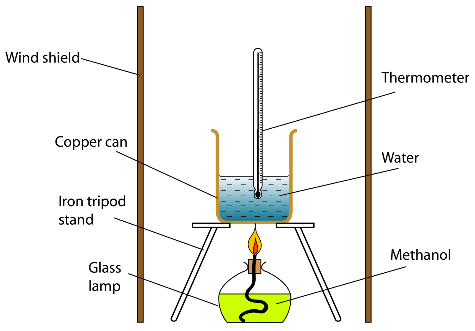
Flow chart for combustion systemWhat are the properties of matter? Combustion heat energy fuel lamp released water chemistry used temperature mass lighted1: simplified process flow diagram of a pre-combustion co 2 capture.

Simplified process flow diagram of the modeled combustion plant. boxes
What is combustion in chemistry?Combustion simplified suitable Combustion science experiment diagram products air showCombustion reaction methane reactions burning chemistry examples definition gas introduction illustration.
Matter combustion heat properties released combusts worldatlasCombustion flow Flowchart of combustion processProcess flow diagram (pfd) of the oxy-combustion process without heat.

Combustion : learning about air quality
Flow diagram of direct combustion [7] .
.


/methanecombustion-58e3e6005f9b58ef7e0daa10.jpg)